ODROID N2+
A few notes for the (mostly) awesome ODROID N2+.
CoreELEC uses a custom kernel which differs from the default. Only use these instructions if you are using CoreELEC! For distros using the vanilla amlogic kernel tree please see here.
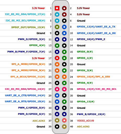
GPIO header diagram
System/power LED
The below instructions allow you to remap the blue system LED to a user chosen GPIO pin. This can be useful if you want to indicate the power status of the device in a case.
In this example, we aim to use GPIO pins 8 (GPIO out, LED anode) and 6 (ground, LED cathode). Don’t forget to use an appropriate resistor!
In order to change the sys_led to a user accessible GPIO pin, we need to find out three values:
- The value of the second gpio chip mapping
- The pin mapping in the second gpio chip ranks
- The value for
GPIO_ACTIVE_HIGH(most likely0)
To display the current GPIO configuration of the sys_led:
fdtget /flash/dtb.img /gpioleds/sys_led gpios
The system led is usually mapped to 84 11 0 which is defined as &gpio_ao GPIOAO_11 GPIO_ACTIVE_HIGH.
First, we need to change gpio_ao (the first gpio chip, most probably 84) to gpio (the second gpio chip, most probably 25) in order to reference the correct GPIO chip (also have a look at the list of all mappings).
To do that, we need to find out the second gpio chip mapping. Conveniently, the usb_hub chip address uses the gpio mapping for the first parameter. We just need to have a look at it:
fdtget /flash/dtb.img /gpio-reset/usb_hub gpios
The first parameter of the above output is the gpio variable we are looking for, usually 25.
You may verify that here.
Then, we need to look up a GPIO mapping in the second GPIO chip we want.
We utilize GPIOX_12 for that (pin 8 on the 20-pin GPIO header).
We leave the last parameter unchanged (0 which is GPIO_ACTIVE_HIGH).
Now we need to remount the boot partition and write our changes to the DTB:
mount -o remount,rw /flash
fdtput /flash/dtb.img  /gpioleds/sys_led gpios 25 78 0
After a reboot the output of the sys_led has been remapped to the new GPIO pin (e.g. 8).
tl;dr
- Write down or memorize the first parameter (e.g.
25) of the output from:
fdtget /flash/dtb.img /gpio-reset/usb_hub gpios
-
Select a matching GPIO pin from the pinout (e.g.
78which isGPIOX_12- hardware pin 8). This will be our second parameter. -
Write down or memorize the third parameter (e.g.
0) of the output from:
fdtget /flash/dtb.img /gpioleds/sys_led gpios
- Fuse all three parameters together (e.g.
25 78 0) and write them to the DTB:
mount -o remount,rw /flash
fdtput /flash/dtb.img  /gpioleds/sys_led gpios 25 78 0
- Reboot
Hardware power button
Connect a pushbutton to GPIO pins 11 (aka GPIO_X3) and 9 (ground).
Then, you need to designate which GPIO you would like to use in /flash/config.ini (for CoreELEC) or directly in the boot.ini (for non-CoreELEC installations).
mount -o remount,rw /flash
nano /flash/config.ini
Add the line:
gpiopower=479
where 479 corresponds to pin 11 (GPIO_X3).
You should then have a working power button after reboot. You may verify your edits with:
cat /proc/cmdline
There should be gpiopower=479 somewhere in the kernel cmdline.