Sonoff Intercom
A recipe for cheap intercom doorbell and buzzer automation with a Sonoff SV and Home Assistant.
With this you can achieve fun stuff like getting notifications when someone rang your doorbell (e.g. the mailman) while you are away or you can buzz someone in automatically.
Parts list
- Sonoff SV
- Transistor (NPN 5V)
- Resistor (1K)
- Soldering equipment and various wires
Total cost: <10EUR
Preparing the Sonoff
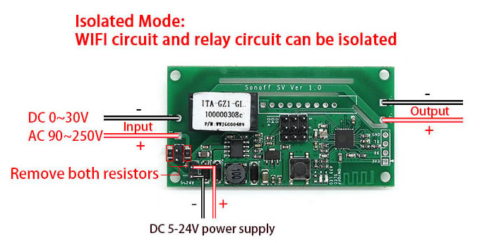
Most door systems work with 3.3V~5V logic for the ring signal and an open/closed circuit for the buzzer. We can process the ring signal input via a transistor to pull GPIO 14 to ground. If there’s 5V on the line (ringer active, current flow from transistor base to emitter), the transistor pulls GPIO 14 to ground (current flow from collector to emitter). The buzzer line is usually higher power and may be connected directly to OUT+ and OUT- so the Sonoff can close the circuit via its relay.
- Desolder the dummy resistors for isolated mode (see illustration above).
- Bridge the input pins (the large input pins IN+ and IN- but not the 5-24V input terminal) in order to have the relay act as a passthrough at OUT+ and OUT- when closed.
- Solder the resistor to the base of the transistor as a pull-down. This will later act as the doorbell sense input.
- Connect the transistor collector to GPIO 14 (IO14 S) and the emitter to ground (IO14 G).
- Power the Sonoff via the bottom left 5~24V DC input terminal, e.g. with a USB power adapter.
We can then connect the Sonoff to the doorbell system (also see example below):
- Connect OUT+ and OUT- to the buzzer circuit (make sure it buzzes on a short).
- Connect the resistor at the transistor base to the ring signal (and make sure the logic is correct: 5V+ on ringer).
- Create a common ground for the doorbell trigger at GPIO 14 to work. Connect the Sonoff GND to the doorbell system ground (make sure to use the DC low voltage ground and not the high power buzzer ground).
Example: Ritto TwinBus 7630
It will bring down and/or damage your whole doorbell system! These TwinBus systems work with low overhead power and are very unstable.

(TwinBus pinout courtesy of Peter from https://www.nicht-trivial.de)
Connections:
- Transistor base goes into blue “Klingelsignal” pin (which will have 5V DC when someone rings the doorbell).
- Top “GND” goes into Sonoff ground.
- “Öffner” and bottom “GND” goes to the “Out+” and “Out-” on the Sonoff.
Flashing the Sonoff
Do not connect 5V to the 3V3 pin.
Download latest tasmota.bin: https://github.com/arendst/Tasmota/releases
Connect the 4pin serial header via a USB adapter (e.g. CH340G orf CP2102) and press and hold the PCB button (GPIO 0) while plugging in the USB adapter to bring the device into flashmode.
Then, flash Tasmota to your Sonoff SV (you may have to reenter the flashmode after each step outlined below):
# Verify a working connection
esptool.py -p /dev/ttyUSB0 read_mac

# Erase the flash before continuing
esptool.py -p /dev/ttyUSB0 erase_flash

# Flash the firmware to the device
esptool.py -p /dev/ttyUSB0 write_flash -fs 1MB -fm dout 0x0 tasmota.bin
Finally, go through the initial configuration steps outlined in the Tasmota wiki: https://tasmota.github.io/docs/Getting-Started/#initial-configuration
Configuration
Access the Tasmota WebUI and configure your module for use with a intercom doorbell and buzzer.
Configuration > Configure Module:
- Module type: Sonoff SV
- GPIO4: Relay2
- GPIO14: Switch2
We need GPIO4 as a (pseudo) relay in order for autodiscovery to work properly. GPIO14 (Switch2) will trigger GPIO4 (Relay2) automatically which will in turn get reported via MQTT. Relay1 is always the hardware relay on the Sonoff SV.
Configuration > Configure MQTT:
- Host: <mqtt_host>
- User: <mqtt_user>
- Password: <mqtt_password>
- Topic: <device_name>
- Full topic: tasmota/%topic%/%prefix%/
Configuration > Configure other:
- (Optional but recommended) Web Admin Password: <secure_password>
- MQTT enable: Checked
- Device name: <device_name>
- Friendly Name 1: buzzer
- Friendly Name 2: doorbell
Main Menu > Console:
# Debounce for the buzzer relay (3s)
PulseTime1 30

# Debounce for the doorbell relay (10s safe disengage)
PulseTime2 100

# Turn on MQTT autodiscovery
SetOption19 1

# (Optional) Configure a NTP server
NtpServer1 <ntp_server>
Now you need to configure the switchmode (these instructions below are for a NPN signal transistor configuration):
- If your doorbell indicates a ring with a pull up (normal low ~0V, ring high 5V+), you need to use “inverse follow mode”:
SwitchMode2 2(GPIO pull high is ON) orSwitchMode2 14(same but without “OFF” event) - If your doorbell only supplies a pull down (normal high, ring low), you need to use “follow mode”:
SwitchMode2 1(GPIO pull to ground is ON) orSwitchMode2 13(same but without “OFF” event)
See also: https://tasmota.github.io/docs/Buttons-and-Switches/#switchmode
In case your ring signal triggers multiple times in short succession try adjusting the switch debounce:
E.g. SwitchDebounce2 200, where 200 is the desired debounce time in 10th of a second.
Configuring Home Assistant
Home Assistant should recognize all MQTT entities via autodiscovery now.
You may additionally configure the doorbell as a binary_sensor for easier automation handling.
Replace intercom with the device name you set earlier:
binary_sensor:
  - platform: template
    sensors:
      intercom_doorbell:
        device_class: sound
        value_template: "{{ is_state('switch.intercom_doorbell', 'on') }}"
Et voilá. All you need now is to configure your automations accordingly.